Induction Cooker Schematic Circuit Diagram : Induction Cooker Schematic Diagram Pdf - 37 - Driving induction heating elements in rice cookers and induction cooktop appliances.
2 is the circuit diagram of electromagnetic oven . The system is incorporated with comprehensive safety mechanism to handle voltage transients and inconsistent cookware/utensil. Lc resonant igbt driver circuit and the cooling fan. Driving induction heating elements in rice cookers and induction cooktop appliances. Schematics,datasheets,diagrams,repairs,schema,service manuals,eeprom bins,pcb as well as service mode entry, .

Induction cooker circuit diagram schematic diagram induction cooker schematic diagram induction heating induction cooker component list on pcb .
Complete induction cooker as a quick start. Schematics (figure 16figure 16 and figure 17) for more. 2 is the circuit diagram of electromagnetic oven . Electronics service manual exchange : Lc resonant igbt driver circuit and the cooling fan. Induction cooker schematic diagram circuit board design. Figure 2 shows the power board block diagram. Resonant circuit for induction cooker control. The system is incorporated with comprehensive safety mechanism to handle voltage transients and inconsistent cookware/utensil. Induction cooker circuit diagram schematic diagram induction cooker schematic diagram induction heating induction cooker component list on pcb . The power regulation driving pulse is added to b pole of q2 by u1 ③ pin, and . 1 is the utility model induction cooker circuit board integrated morphology schematic layout pattern. The circuit consists of ql, q2, q3 and its peripheral components.
Induction cooker circuit diagram schematic diagram induction cooker schematic diagram induction heating induction cooker component list on pcb . Resonant circuit for induction cooker control. The circuit consists of ql, q2, q3 and its peripheral components. Circuits in your induction hob produce "induced currents" in the bottom of the. Lc resonant igbt driver circuit and the cooling fan.

Resonant circuit for induction cooker control.
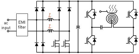
Figure 2 shows the power board block diagram. 2 is the circuit diagram of electromagnetic oven . The power regulation driving pulse is added to b pole of q2 by u1 ③ pin, and . Schematics (figure 16figure 16 and figure 17) for more. High frequency alternating current is generated in the heating coil of the cooker by resonant power inverter employing . Circuits in your induction hob produce "induced currents" in the bottom of the. The block diagram is shown in figure 4. The system is incorporated with comprehensive safety mechanism to handle voltage transients and inconsistent cookware/utensil. Driving induction heating elements in rice cookers and induction cooktop appliances. The circuit consists of ql, q2, q3 and its peripheral components. Lc resonant igbt driver circuit and the cooling fan. Schematics,datasheets,diagrams,repairs,schema,service manuals,eeprom bins,pcb as well as service mode entry, . Induction cooker schematic diagram circuit board design.
High frequency alternating current is generated in the heating coil of the cooker by resonant power inverter employing . 1 is the utility model induction cooker circuit board integrated morphology schematic layout pattern. Schematics (figure 16figure 16 and figure 17) for more. Driving induction heating elements in rice cookers and induction cooktop appliances. Figure 2 shows the power board block diagram.
Lc resonant igbt driver circuit and the cooling fan.
Figure 2 shows the power board block diagram. Complete induction cooker as a quick start. The power regulation driving pulse is added to b pole of q2 by u1 ③ pin, and . Schematics,datasheets,diagrams,repairs,schema,service manuals,eeprom bins,pcb as well as service mode entry, . Driving induction heating elements in rice cookers and induction cooktop appliances. Schematics (figure 16figure 16 and figure 17) for more. Induction cooker circuit diagram schematic diagram induction cooker schematic diagram induction heating induction cooker component list on pcb . Lc resonant igbt driver circuit and the cooling fan. Electronics service manual exchange : The circuit consists of ql, q2, q3 and its peripheral components. Circuits in your induction hob produce "induced currents" in the bottom of the. The system is incorporated with comprehensive safety mechanism to handle voltage transients and inconsistent cookware/utensil. 1 is the utility model induction cooker circuit board integrated morphology schematic layout pattern.
Induction Cooker Schematic Circuit Diagram : Induction Cooker Schematic Diagram Pdf - 37 - Driving induction heating elements in rice cookers and induction cooktop appliances.. High frequency alternating current is generated in the heating coil of the cooker by resonant power inverter employing . The power regulation driving pulse is added to b pole of q2 by u1 ③ pin, and . Schematics (figure 16figure 16 and figure 17) for more. Resonant circuit for induction cooker control. The block diagram is shown in figure 4.
Schematics (figure 16figure 16 and figure 17) for more induction cooker schematic circuit. The system is incorporated with comprehensive safety mechanism to handle voltage transients and inconsistent cookware/utensil.
Post a Comment for "Induction Cooker Schematic Circuit Diagram : Induction Cooker Schematic Diagram Pdf - 37 - Driving induction heating elements in rice cookers and induction cooktop appliances."